Hoyt KW4000 User Manual
Browse online or download User Manual for Welding System Hoyt KW4000. Hoyt KW4000 User's Manual
- Page / 15
- Table of contents
- BOOKMARKS
Summary of Contents
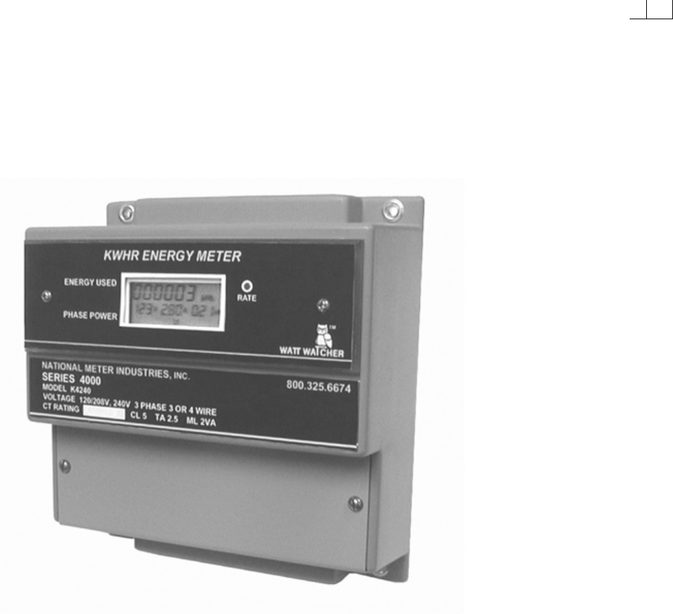
SERIES 4000ENERGY METERWATT WATCHER INSTALLATION AND OPERATION MANUAL HOYT ELECTRICAL INST. WORKS INC. PENACOOK, NEW HAMPSHIRE
COMMON TERM USED WITH METER READINGSVOLTAGE: The potential between phase and neutral or phase to phase. This can be 120 to 480 volts dependingupon t
SPECIFICATIONS:Power Supply:Single Phase 230 or 480 VAC in applicable modelsVoltage Tolerance –20% to +20%Frequency 50 to 60 Hz.Power 6 VAOperating Te
COMMUNICATION NETWORKOne or more meter can be connected to a PC so you can read all the parameters at one centrallocation. There is a terminal block m
MODBUS PROTOCOLThe Series 4000 Energy Meter can communicate by means of the ModBus protocol as described below:When the meter communicates with MoBus,
ENGINEERING SPECIFICATIONS FOR K4000 SERIES THREE PHASE KILOWATTHOUR METER1.1 GENERALSubmeter for three phase energy billing of kilowatt hours1. Mete
Page 2 Three-Phase meter specifications cont.4. Accuracy and Listings:a. The meter shall comply with ANSI C12.16 Electricity Metering Standardsb. F
INDEX Short Cut to Resetting the Demand Readings Inside Front CoverIntroduct
INTRODUCTION:You now have in your possession one of the most reliable and highly accurate meters evermanufactured.To insure proper installation and pe
MAIN FEATURES:The Series 4000 is factory programmed offering one model for both 3 or 4 wire services orbranch circuits. The factory has program the A
THE SERIES 4000 CONNECTION TERMINALSTerminal No. Designation DescriptionL1 – L2 Power Supply Power Supply at 230 or 480 VACRelay Pulse Reed RelayRS 4
CONNECTION DIAGRAMS FOR THE SERIES 4000Three Phase 4 wire service, which also includes a Hi-leg Service. 1. Use either 5 Amp in-line fuses or a 15 A
WIRING INSTRUCTIONS1. All wiring to this meter must comply with National Electric Code or any local codes that areapplicable. A grounding conductor
Split Core Current Transformers (Model NMI-TP-Series)Please refer to the above drawing:1. Remove and dispose of the packaging materials 2. To remov
Split Core Current Sensor Model (NMI 1250-400)The secondary side of these split core transformers is 110 milli-volts at 400 Amps.You need to cap the b
© 2020, manymanuals.com. All rights reserved. | 0.627 s |
 Manymanuals.com
 Manymanuals.de
 Manymanuals.fr
 Manymanuals.it
 Manymanuals.pl
 Manymanuals.cz
 Manymanuals.es
 Manymanuals-pt.com
Comments to this Manuals